Power sharing |
  
|
Power sharing |
|
See Multi-MPPT inverters for generalities.
By default, PVsyst assumes that an inverter with 2 MPPT inputs behaves as 2 identical inverters of half the power. That is, each MPPT input will have a "nominal power" of half the power of the full inverter.
For example, an inverter of 10 kW with 2 MPPT will behave as to 2 independent inverters of 5 kW.
However during operation, the real inverters have the possibility of sharing the total output nominal power between their different MPPT inputs.
On request, PVsyst may take this PNom sharing into account (button "Power sharing" just below the inverter "Open" button, appearing only when it is applicable).
There are several possible situations, detailed below:
-Inverter inputs of a same inverter in a same sub-array
-Inverter MPPT inputs on 2 or more sub-arrays with different array configurations
-"String inverters" with several MPPT inputs
-2 sub-arrays with different orientations
-Several inverters in a sub-array with "Mixed orientation"
Inverter inputs of a same inverter in a same sub-array
When you define several MPPT inputs of a given inverter in one sub-array:
| - | If you check the option "Use Multi-MPPT feature", each MPPT input will be considered as an individual inverter with fixed PNom(MPPT) = PNom(Inv) / NbMppt. |
| Therefore if you have for example 3 strings to be shared out onto 2 MPPT inputs, one input will receive 2 strings and the other one 1 string. Therefore a higher PNom Ratio on the first input, which may lead to overload losses. |
| - | If you uncheck the option "Use Multi-MPPT feature", the inverter input will be considered as a whole, there will be a "natural" Power sharing on your imbalanced inputs: one will take 2/3 of the Pnom, and the other one 1/3. This will minimize the overload losses. |
Inverter MPPT inputs on 2 or more sub-arrays with different array configurations
When you have several MPPT inputs (of a same inverter) with different array configurations (PV module type, number of modules in series), you have to define one sub-array for each configuration.
In this situation, the option "Use Multi-MPPT feature" should be checked of course.
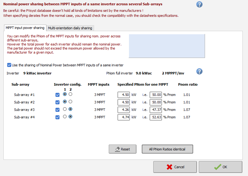
In this case, at design time, the button "Power sharing" allows to pre-define the nominal power PNom allocated to each MPPT input (in each sub-array) during the simulation. This will lead to a more accurate simulation of the overload losses, but it is the responsibility of the user, to make sure that the power sharing settings are compatible with the inverter manufacturer specifications. The 'Power Sharing' tool will allow to allocate a specified PNom, according to the effective nominal power of the connected modules. The sub-arrays concerning a given physical Inverter are interdependent: if you define Pnom(MPPT1) in one sub-array, the Pnom(MPPT2) will be Pnom(Inv) - Pnom(MPPT1). Only sub-arrays containing a same inverter model can perform the power sharing among each other. Sub-arrays that are included in the power sharing should be marked by a CheckBox on the left. In complex cases with more than two sub-arrays, radio buttons allow to group the sub-arrays belonging to the same inverter. For example:
This is easy when you have only 2 kinds of MPPT (2 sub-arrays), but may be more difficult with 3 or more combinations, or non-equal numbers of inverter inputs in each sub-array: in this case PVsyst will check the feasibility of your choices and associations, but cannot always propose a general solution.
"String inverters" with several MPPT inputs
String inverters with 4, 6 or even more MPPT inputs become now common on the market. These devices are usually designed for receiving one only string on each input (sometimes 2). This is attested by the specification of a max. current per MPPT specified around 10 A (one string) or 20 A (2 strings).
With these devices people are lead to define one or two strings on each input, with possible overpower with respect to the nominal power of one MPPT input.
When you are using the "Power sharing" option between several of these MPPT inputs, you should ensure that within each sub-array, the number of strings is a multiple of the number of MPPT inputs. I.e. you should avoid having a mix of one string and two strings on different MPPT's. Because the power sharing of the PVsyst model acts between sub-arrays, but not within a sub-array.
Be careful: as in the PVsyst inverter database, there is no information about the maximum power (or current) for each individual MPPT input, it is your responsibility to check in the data sheets whether the allocated power is compatible with the manufacturer's specifications. PVsyst puts a general limit to the sharing ratio, which is modifiable in the Hidden parameters.
Now in some cases the manufacturers may specify a maximum current per input, using the Vmpp_PMax parameter. See Grid Inverters: Main Parameters, especially concerning the variables Vmpp_PMin and IMax_InMPPT.
2 sub-arrays with different orientations (for example with "domes")
When you have 2 orientations, the array power in each orientation will evolve differently during the day. It may be interesting to use Multi-MPPT inverters, with one MPPT input for each orientation.
The maximum power of one orientation will not arise at the same time during the day, so that you can "undersize" the inverter.
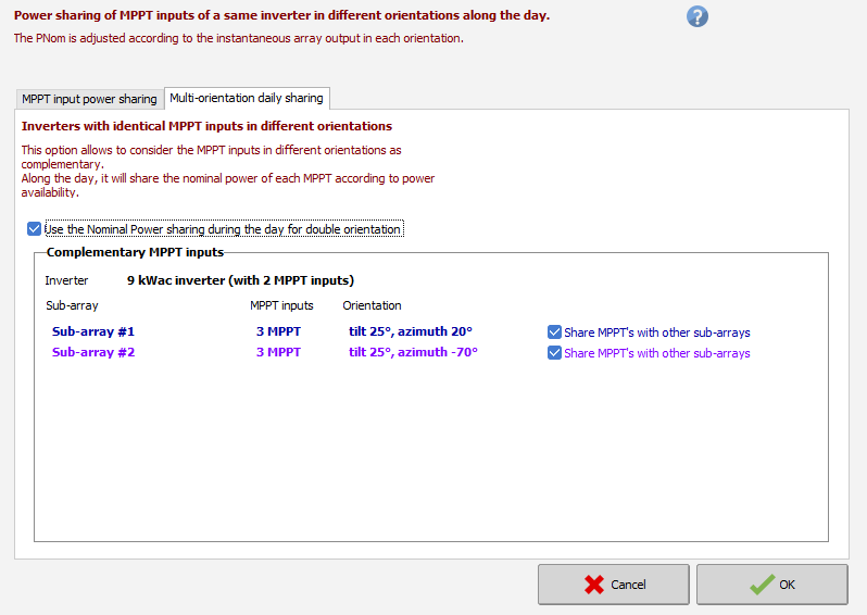
In this situation, the PNom of each complementary MPPT input should be shared according to the hour of the day. This is done during the simulation: at each time step, the PNom of each MPPT will be adjusted according to the incident energy in each orientation.
The setup for daily sharing can be setup via the power sharing window, which will show a daily sharing tab.
Several inverters in a sub-array with "Mixed orientation"
In PVsyst, you have the possibility of defining 2 different orientations for a same sub-array.
In this case you have to attribute each string of this sub-array to a given orientation.
If you have several inverter inputs, there are two ways of distributing the strings on these inputs:
- Either you consider minimizing the mismatch: you connect all the strings of one orientation to a set of inverter inputs, all the strings of the other orientation to another set of inverter inputs. In between both sets there may be one inverter with strings of different orientations, for which the I/V curves will be mixed.
- Or you connect strings of both orientations on each inverter input (or complementary MPPT inputs): this configuration would be suited for "domes" as in the previous situation.
You can choose between the first or the second configuration using the two radio buttons in the group "Distribution of Inverter inputs acc. to orientation". The PNom sharing will concern the full inverters and will be performed during the simulation.