External transformer losses |
  
|
External transformer losses |
|
Defining external transformers
In many big PV installations (in the MWp range), the transformer is not part of the inverter, but an external device directly connected to the MV or even HV grid.
You have the opportunity of defining:
- One or several Medium voltage inverters in the whole system (they will be equally shared by all the inverter outputs)
- One Medium Voltage inverter in each sub-array. This may be different in different sub-arrays, but each sub-array has to define a transformer.
- Eventually a High voltage transformer (MV => HV at the injection point).
Transformer definition
The main losses associated with the transformer are:
- The iron losses (mostly due to hysteresis and eddy currents in the core) are proportional to the square of the core flux, i.e. to the square of the voltage. As we have a constant grid voltage, this is considered as a constant loss. PVsyst proposes a default value of 0.1% of the reference nominal power.
NB: The iron loss remains active and constant during the whole connecting time, and may represent a significant energy loss. This appears as negative E_Grid system yield during the night. Therefore it may be economically profitable to foresee a switch for disconnecting the transformer from the grid during night. The option "Night disconnect" is available for the simulation.
- The ohmic losses, often named copper losses, either in the primary and in the secondary windings. These may be represented by an equivalent resistance of the primary, and the loss will be computed as R * I² during the simulation. As for the wiring losses, this means that the relative loss is proportional to the current (or power).
Generic definition
As for the wiring losses, PVsyst proposes a generic initial Ohmic loss relative value, for the early stage of the project's development.
This is defined as a percentage loss with respect to the reference nominal power, i.e. either PNomPV(ac) or PNom(Inv).
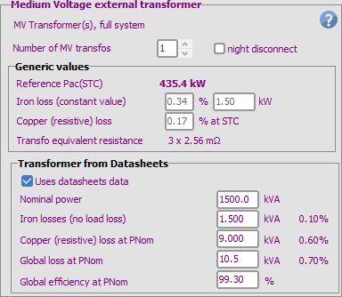
Datasheets definition
You can also define the real parameters of the chosen transformer (recommended).
The main information required is the Nominal power, the Iron loss (often named "no load loss") and the Copper loss.
The datasheets may specify either the global loss at PNom, or the global efficiency, from which PVsyst will deduce the copper loss.
Defining the real parameters from the Transformer's datasheet will fix the Generic values.
Relationship between the Generic and Datasheets values.
Determination of the parameters using Transfo's specified parameters at PnomTrf:
The transformer manufacturer may specify, either in terms of power:
| - a nominal power | PNomTrf |
| - a global loss under this nominal power | PGlobLossTrf [kW] |
| - an iron loss under no load | PIronLssTrf [kW] |
| => the resistive power loss is | PResLssTrf = (PGlobLossTrf - PIronLssTrf) [kW] |
or alternatively in terms of loss factor at PNom :
| - a global loss factor under PNom | FGlobLossTrf [%] = 100 * PGlobLossTrf / PNomTrf |
| - an iron loss factor under no load | FIronLssTrf [%] . = 100 * PIronLssTrf / PNomTrf |
| - a resistive loss factor | FResLssTrf [%] . = 100 * PResLssTrf / PNomTrf |
We can deduce the Transformer resistance (which is the basic parameter during the simulation):
| - Nominal current at nominal power | INomTrf = PNomTrf / (UNom * Sqrt(3)) |
| - => Transformer equivalent resistance | ResTrf = PResLssTrf / INomTrf ² (for one wire) |
Remember that the resistive power loss goes with the square of the current, i.e. the Operating power Poper.
Passing to the PVsyst parameters, referenced to PnomAC:
In PVsyst the transformer losses are specified as percentages of the reference nominal power (either PNomPV(ac) or PNom(Inv)).
NB: this PNom_Ref. is a definition for the calculations. This should be considered as not affected by the inverter or grid injection limitations.
| - | PIronLss(PVsyst) = PIronLssTrf [kW] (doesn't depend on PNom) |
| - | FIronLss(PVsyst) = PIronLssTrf [kW] / PNom_Ref = FIronLssTrf * PNomTrf / PNom_Ref |
| - | PResLss(PVsyst) = PResLssTrf * PNom_Ref ² / PNomTrf ² |
| - | FResLss(PVsyst) = PResLss(PVsyst) / PNom_Ref = FResLssTrf * PNom_Ref / PNomTr, |
i.e. the opposite behaviour as the Iron losses (the higher thePNom_Ref, the higher the resistive loss factor).
As an example:
Transformer parameters from the datasheets:
| - | PNomTrf = 1.5 MW |
| - | PIronLssTrf = 1,5 kW (i.e. 0.1% of PNomTrf) |
| - | PGloblossTrf = 16.5 kW (under nominal power PnomTrf) |
=> The resistive loss is PGloblossTrf - PIronLssTrf = 15 kW (i.e. 1.5% of PnomTrf).
In PVsyst, if we choose PNom_Ref = PNomPV(ac), and if we have a PV system of 1.05 MWp with an inverter efficiency = 95% @PNom
=> PnomPV(ac) = 1 MW (the PNomPV(ac) value appears as "Pac" on the AC circuit loss dialog).
Applying the previous expressions:
| - | PIronLss(PVsyst) = 1.5 kW |
| - | FIronLss(PVsyst) = 1.5 kW / 1 MW = 0.15% |
| - | PResLss(PVsyst) = 15 kW * (1 MW / 1.5 MW)² = 15 kW * 0.444 = 6.66 kW |
| - | FResLss(PVsyst) = 6.66 kW / 1 MW = 0.66% |
The values 0.15% and 0.66% are those to be introduced as generic values in PVsyst.